Table of Contents
Case Study: CAN Bus Troubleshooting in Mercedes-Benz GL W164 ; DSR & ESP Warning Repair
Customer Complaint
A Mercedes-Benz GL W164 arrived at the workshop with multiple dashboard warnings and electrical malfunctions. The driver reported:
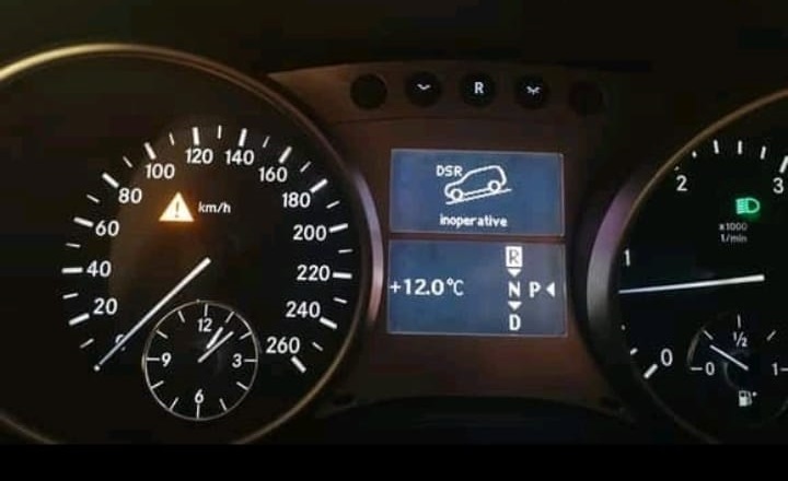
- – “DSR (Direct Steer Response) Malfunction” message
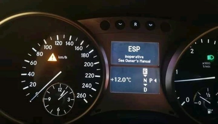
- – “ESP (Electronic Stability Program) Unavailable” message
- – Turn signals, wipers, back-up camera, and Parktronic system all inoperative
- – Engine fan running continuously on high speed (more information in this article)
These symptoms suggested a network-level communication failure rather than isolated component issues.
Step 1: Initial Diagnostic Scan
The technician connected Mercedes XENTRY to perform a complete vehicle scan.
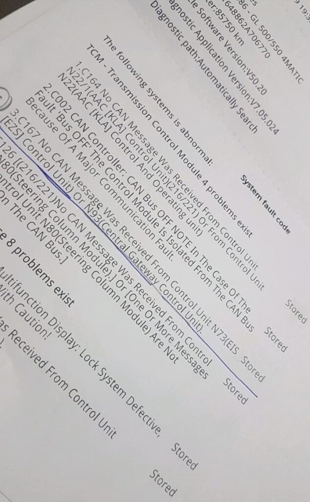
The diagnostic report showed multiple “No Communication” errors across various systems a typical indicator of CAN Bus network disruption.
Preliminary finding:
Faults pointed toward a possible Central Gateway (CGW) malfunction or shorted wiring in the interior CAN segment linking the Parktronic, amplifier, and SAM modules.
Understanding the System
The Controller Area Network (CAN Bus) is the backbone of all Mercedes-Benz communication.
Each module (ABS, ESP, CGW, SAM, etc.) exchanges data through CAN High (CAN-H) and CAN Low (CAN-L) lines.
When one module or connector becomes shorted, wet, or corroded, it can bring down the entire communication bus, leading to multiple system warnings exactly like those observed in this case.
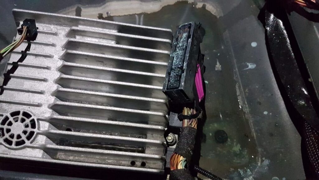
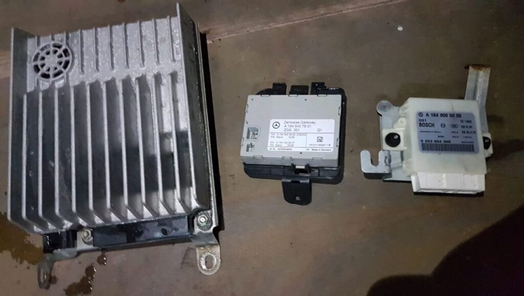
Step 2: Physical Inspection
Following the wiring layout, the technician traced the CGW and related modules located under the passenger seat a known moisture-prone area in the GL/ML W164.
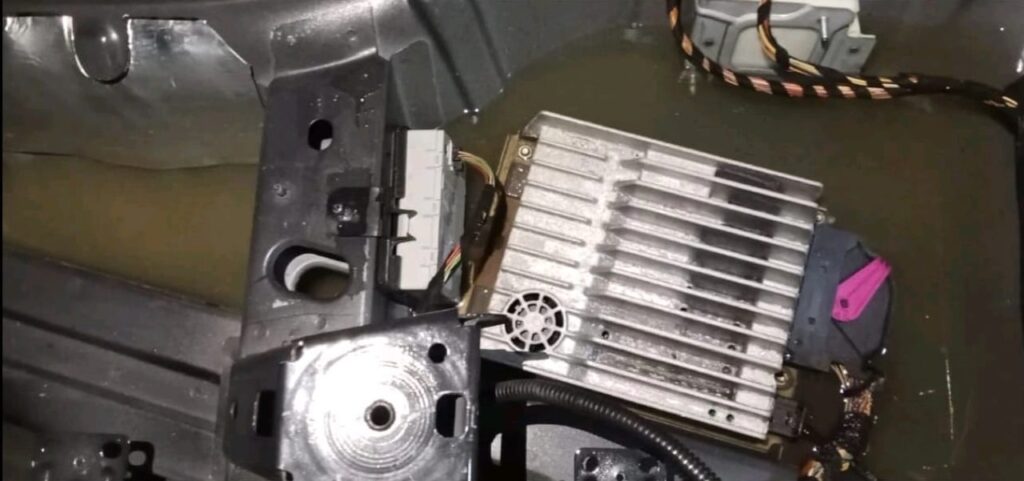
Findings:
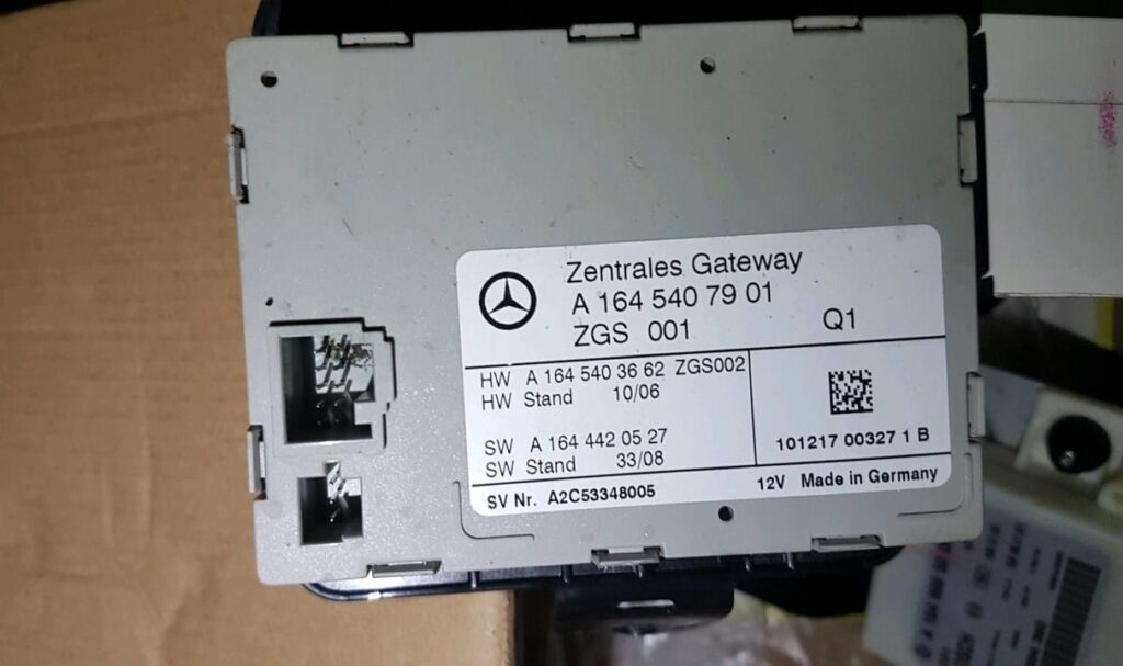
- – The CGW module was dry and intact.
- – However, the Parktronic and amplifier modules were submerged in water due to a blocked sunroof drain.
- – Several harness connectors showed oxidation and green corrosion.
The water intrusion explained the network instability and multiple communication losses.
Step 3: CAN Bus Signal Testing
Using a digital multimeter, the technician validated the electrical health of the CAN network.
Test Procedure
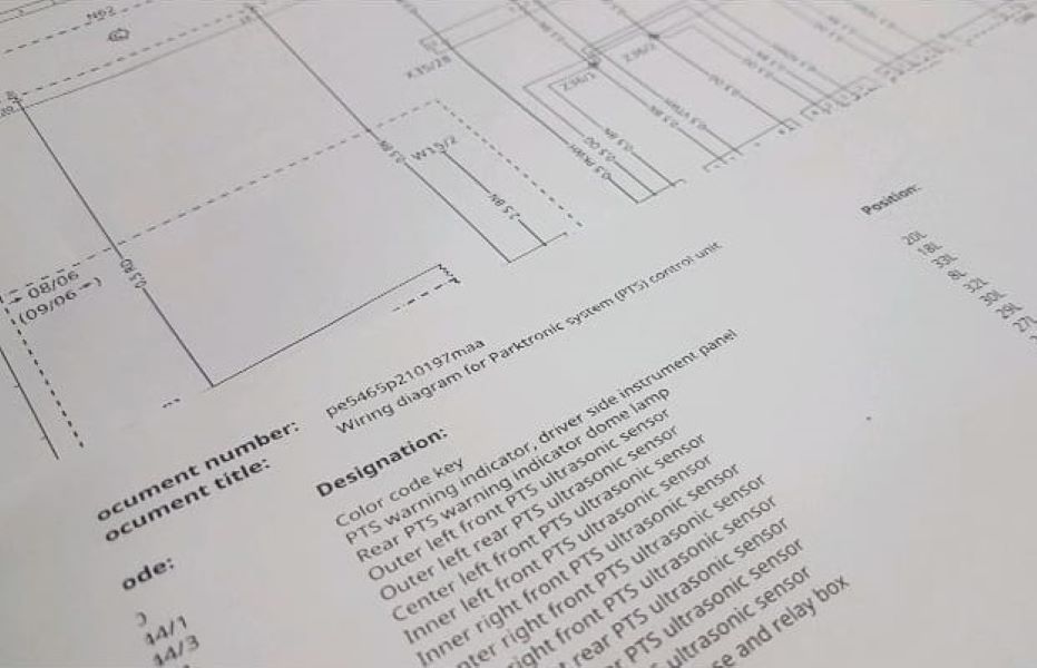
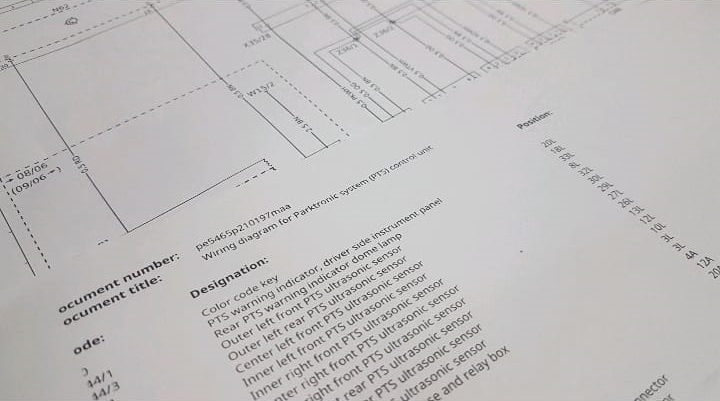
- 1. Identify CAN wires: Located the CAN-H and CAN-L lines in the affected segment (as per wiring diagram).
- 2. Continuity check: Ensured no breaks or shorts between CAN-H and CAN-L.
- 3. Resistance measurement:
- – Measured resistance between CAN-H and CAN-L → ~60 Ω (within normal range; two 120 Ω terminations in parallel).
- 4. Voltage test (Ignition ON):
- – CAN-H ≈ 2.7 V, CAN-L ≈ 2.3 V → balanced, but slight fluctuation due to corroded connectors.
The readings indicated that bus resistance and topology were healthy, but connectors and localized oxidation were disrupting clean signal transmission.
Step 4: Identifying the Root Cause
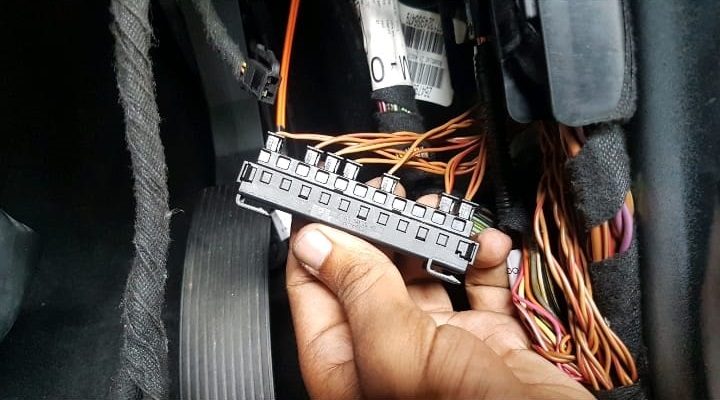
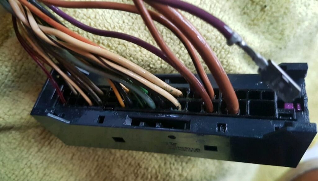
After reviewing live data and physical inspection, the Parktronic control unit (A42/4) was identified as the primary fault source:
- – The module exhibited internal water damage.
- – When unplugged, network stability improved, and the other systems (wipers, turn signals) momentarily came back online.
Conclusion:
The water-damaged Parktronic module was shorting the CAN line, pulling down communication for the other connected systems.
Step 5: Repair Procedure
- 1. Replace the Parktronic Control Module
- – A new genuine Mercedes-Benz module was installed and coded using XENTRY.
- – The Parktronic system became fully operational.
- 2. Address Water Intrusion
- – The technician dried the carpet and module housing thoroughly.
- – All affected connectors and harnesses were cleaned using electronic contact cleaner and re-pinned where necessary.
- – Sunroof drains were cleared to prevent future water entry.
- 3. CAN Bus Verification
- – Re-tested CAN-H/CAN-L continuity, voltage, and resistance.
- – No further fluctuations or signal errors detected.
- – Final quick test confirmed full communication with all modules.
Step 6: Validation & Results
After the repair:
- – No more DSR or ESP warnings on the dashboard.
- – Turn signals, wipers, and back-up camera functioned normally.
- – Engine fan returned to normal operation (previously defaulted to high-speed “failsafe mode” due to lost communication).
- – CAN Bus integrity verified via XENTRY all modules online, no active faults.
Outcome:
The GL W164 was restored to full working order. The repair addressed both electrical network recovery and preventive sealing against moisture intrusion.
Root Cause Analysis
| Problem Area | Description | Impact |
|---|---|---|
| Parktronic module (A42/4) | Water-damaged, shorted internally | Pulled down the CAN network |
| Wiring harness | Corrosion in connectors under passenger seat | Caused intermittent signal loss |
| Drainage system | Blocked sunroof drain | Allowed water accumulation under carpet |
Technician Takeaway
- – Always check for water ingress when facing multi-system electrical faults in W164/W166 models. Moisture is a leading cause of CAN communication failures.
- – Measure both resistance and voltage ; resistance alone can look fine even if connectors are oxidized.
- – Isolate modules methodically ; unplug one at a time to see when communication recovers.
- – After replacing any CAN-connected module, perform SCN coding and network synchronization with XENTRY.
Quick CAN Bus Testing Reference
| Test | Expected Value | Indicates Fault If… |
|---|---|---|
| Resistance (CAN-H ↔ CAN-L) | ~60 Ω | Reads 0 Ω (short) or 120 Ω (missing terminator) |
| Voltage (Ign. ON) | CAN-H ≈ 2.5–3.5 V / CAN-L ≈ 1.5–2.5 V | One line stuck high or low |
| Continuity | < 1 Ω | Open or corroded joint |
| Oscilloscope pattern | Symmetric waveform | Missing signal or heavy noise |
Related Diagnostic Resource
If your Mercedes shows multiple electrical or communication warnings from ESP to lighting or wipers explore this in-depth troubleshooting hub:
Mercedes Electrical Problems: Fix SAM, ECU & CAN Bus Faults
A complete diagnostic resource covering control module power loss, CAN and LIN communication faults, and short circuit tracing across all Mercedes models.
Together with this case study, it provides a complete roadmap for diagnosing complex Mercedes network faults.
Conclusion
This case demonstrates the importance of combining digital diagnostics with physical inspection when troubleshooting CAN Bus issues.
The Parktronic module’s water intrusion caused cascading communication failures across the ESP, DSR, and SAM networks.
By applying structured diagnostics voltage testing, resistance checks, and segment isolation the technician efficiently located the fault, restored full functionality, and implemented preventive measures.
In network-related Mercedes repairs, CAN and LIN diagnostics are never isolated they depend on healthy power supply, grounding, and environmental protection.
Always treat electrical integrity as the foundation of communication reliability.
— Salim, Mercedes Expert
Independent specialist in Mercedes-Benz diagnostics, CAN Bus analysis, troubleshooting case studies, and EV systems.