
Table of Contents
Mercedes LIN-Bus Issue: Why It Happens & How to Fix It
What the warning means
A LIN-Bus communication error (e.g., “LIN BUS 1 Faulty”, “Front Left Malfunction”) means a master ↔ slave node on the Local Interconnect Network stopped talking. In Mercedes, LIN typically handles non-critical comfort systems (HVAC stepper motors, seat/mirror modules, interior lighting, alternator smart charging, belt buckle sensors). When it fails, you may see comfort features inoperative, and in some cases SRS/Pre-Safe messages if those sensors ride the same LIN segment.
For power-supply and communication faults that mimic or cause LIN errors, see:
Mercedes Electrical Problems: Fix SAM, ECU & CAN Bus Faults a complete diagnostic hub for module power loss, short circuits, and network errors.
Common Causes & Symptoms
| Cause | Real-world symptoms | Quick diagnostics & fix |
|---|---|---|
| Faulty LIN slave (HVAC flap motor, mirror, seat module, belt buckle sensor, alternator regulator) | Single function dead; related DTC; others OK | Unplug suspected slave → see if network recovers; replace faulty node and clear codes |
| Open/corroded LIN wire or connector | Intermittent faults; multiple features cut in/out | Wiggle test; inspect splices/grounds; repair harness/connector; re-pin if needed |
| Sleeping/misconfigured module after low voltage | Works after ignition cycle; fault returns after park | Battery/charging test; wake up/reinitialize with scan tool; adaptation reset |
| Master/gateway fault (e.g., front SAM HVAC master, SRS gateway) | Many slaves on same segment offline | Scope or substitute master; flash/update or replace master/gateway |
Diagnostic Workflow (works in any Mercedes platform)
- 1. Scan first, don’t guess
Read all control units with XENTRY (or equivalent). Note LIN DTCs (e.g., U100887 “LIN Bus 1 – message missing”), and identify which master reports which slaves as missing. - 2. Map the segment
From wiring info, list the master (often a climate panel/SAM/SRS gateway) and its slave nodes on that LIN line. - 3. Voltage sanity
Check battery ≥12.4 V (rest) and 13.8–14.4 V (running). Low voltage makes LIN nodes sleep. - 4. Isolate by unplugging slaves
One at a time, unplug each slave on the segment. If the network recovers (DTCs change), the last unplugged slave is suspect. - 5. Harness & connector check
Inspect the single-wire LIN line, shared grounds, and splices under seat, center console, behind HVAC panel. Repair corrosion, broken pins, poor splices. - 6. Master/gateway decision
If multiple slaves remain missing with good wiring, flash/update master; if no change, replace master. - 7. Finalize
Clear DTCs, wake nodes, run functional tests (flap positions, mirrors, seat moves, buckle status), and road-test.
Case Study: 2018 Mercedes C300 (W205) LIN BUS 1 Fault Leading to SRS Warning
Customer Complaint
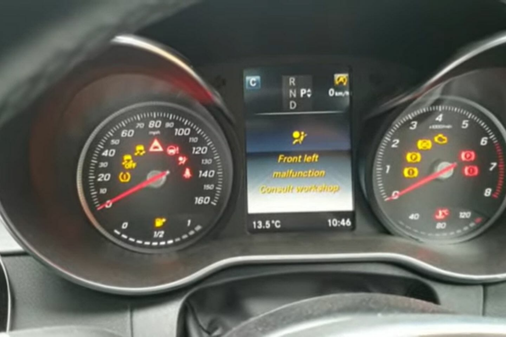
The owner of a 2018 Mercedes-Benz C300 (W205) reported that the airbag warning lamp was illuminated on the instrument cluster, accompanied by the message:
“Front passenger malfunction consult workshop.”
Despite this alert, all comfort features such as the seat adjustment, HVAC, and mirrors appeared functional. However, given the safety-critical nature of the SRS (Supplemental Restraint System), the vehicle was brought in for immediate diagnostic testing.
Fault Memory , Initial Scan
Using Mercedes XENTRY Diagnosis, a complete system scan revealed several stored Diagnostic Trouble Codes (DTCs) in both the SRS and body network systems:
SRS Control Unit (N2/10):
- – B275113 – Sidebag “front passenger” squib has a malfunction (open circuit)
- – B274F13 – Pelvis airbag “front passenger” squib has a malfunction (open circuit)
- – B005213 – Belt buckle “front passenger” has a malfunction (open circuit)
Body/Network Control:
- – U100887 – LIN Bus 1 has a malfunction; message missing
These codes immediately suggested a communication failure on the LIN BUS 1 network, which serves multiple restraint-related modules on the passenger seat.
Step 1: Battery & Power Supply Verification
Electrical communication networks such as LIN and CAN are highly sensitive to voltage stability.
- – Battery voltage: 12.5 V (engine off) / 13.9 V (engine running)
- – Ground resistance: < 0.1 Ω
All readings were within specification. Power supply was stable, ruling out voltage drop or battery degradation as the cause of communication loss.
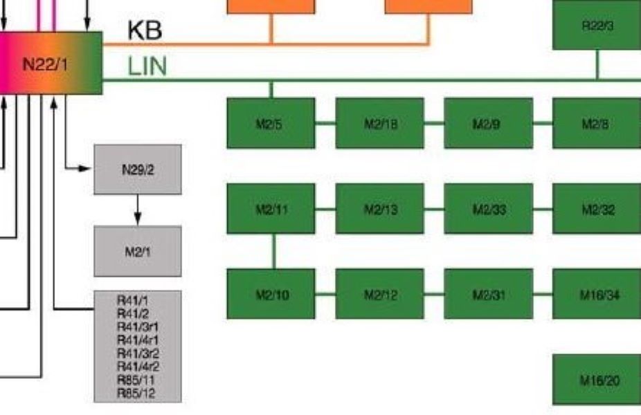
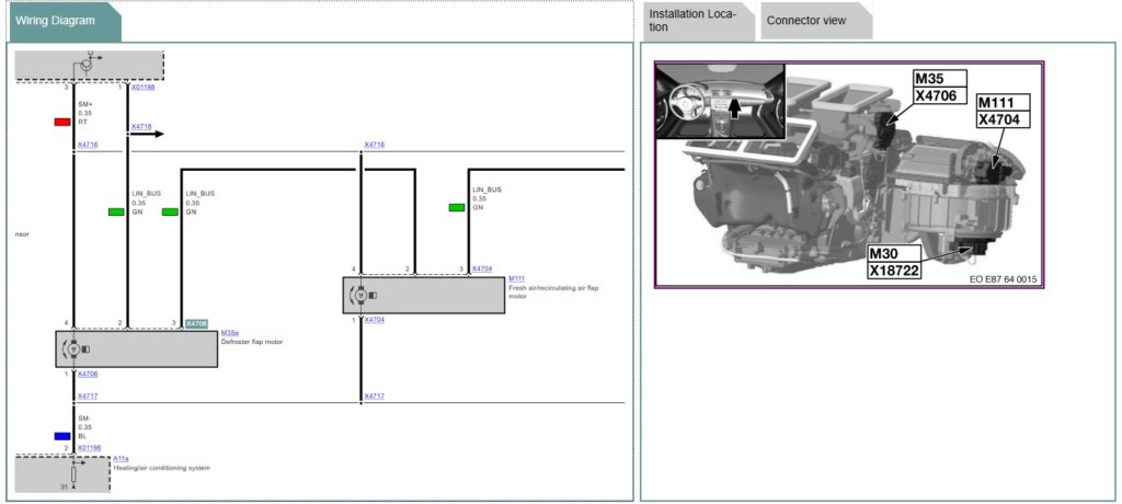
Step 2: LIN Segment Mapping
Using the wiring diagram for the W205 C-Class, the technician identified that the passenger seat belt buckle sensor, seat occupancy sensor, and side airbag modules share the LIN BUS 1 segment, with the SRS control unit acting as the master node.
This layout meant that a single shorted slave node (such as a faulty buckle sensor) could pull down the entire communication line and trigger multiple “open circuit” errors, even when the airbags themselves were operational.
Step 3: Slave Isolation Test
To identify the defective node, the technician performed a sequential disconnection test:
- 1. Each LIN slave connector under the passenger seat was unplugged one by one.
- 2. After each disconnection, the fault memory was read to check whether communication was restored.
Findings:
When the passenger belt buckle connector was unplugged, the U100887 fault changed state and communication resumed temporarily.
Reconnecting the same component caused the LIN fault to return instantly.
Conclusion:
The belt buckle sensor, which communicates its latch status over LIN BUS 1, was internally shorted acting as a bus pull-down and silencing other devices on the same network.
Step 4: Connector & Harness Inspection
Upon visual inspection, the buckle’s under-seat connector showed traces of oxidation and green corrosion, consistent with moisture ingress a common problem in vehicles exposed to damp floor mats or spilled liquids.
- – The connector was cleaned, contacts re-pinned, and the harness was rechecked for continuity.
- – While communication briefly stabilized, intermittent failures persisted during movement of the seat frame.
This confirmed that both the buckle sensor and connector had internal degradation beyond repair.
Step 5: Component Replacement & Reprogramming
A new OEM passenger belt buckle assembly (with integrated LIN sensor) was installed.
Using XENTRY:
- – All previous SRS and LIN BUS fault codes were cleared.
- – The SRS control unit was reinitialized to recognize the new LIN slave.
- – A post-repair quick test confirmed communication integrity.
Step 6: Validation & Final Checks
After reassembly:
- – The airbag warning light turned off immediately after ignition ON.
- – No LIN or SRS DTCs were present after multiple ignition cycles.
- – A 20-minute dynamic road test confirmed stable communication with no network dropouts.
All occupant detection, buckle signals, and restraint functions operated normally.
Root Cause Summary
| Fault Area | Description | Impact |
|---|---|---|
| LIN slave failure | Passenger belt buckle sensor shorted internally | Pulled down LIN BUS 1 communication |
| Connector corrosion | Moisture intrusion under seat | Caused intermittent signal degradation |
| SRS false codes | Control unit lost LIN communication | Misinterpreted missing data as “squib open” faults |
Technician Takeaway
- – Don’t replace airbags prematurely. Multiple “open circuit” SRS codes can be symptoms, not root causes, of a LIN communication failure.
- – Always inspect LIN wiring and connectors first, especially under seats where corrosion and movement are common.
- – Voltage stability and ground integrity are critical; always test before diving into module replacements.
- – After replacing any LIN node, perform a full system adaptation to prevent recurrence.
Pro Tips (save hours)
- – Unplug-to-restore is your fastest isolator on LIN. If the bus recovers when a slave is unplugged, you found the troublemaker.
- – Low voltage = sleepy slaves. Always test the battery/alternator before deep-diving the network.
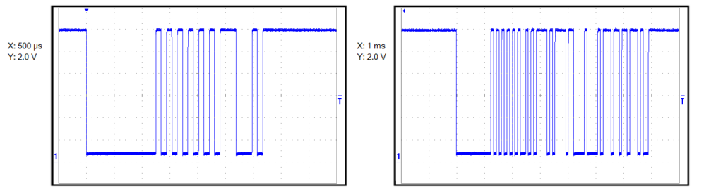
- – LIN ≠ CAN. It’s one wire, pull-down signaling. A single bad node can silence the whole segment.
- – After replacing slaves/masters, run adaptations (HVAC flap end-stops, seat indexing) and validate live values.
Related Diagnostic Resource
If you’re diagnosing communication or voltage-related faults in Mercedes control modules, explore:
Mercedes Electrical Problems: Fix SAM, ECU & CAN Bus Faults; a complete diagnostic hub covering control module power loss, short circuits, and network communication errors across Mercedes models.
DIY vs Professional
| Task | DIY-friendly | Pro recommended |
|---|---|---|
| Read/clear DTCs, wake nodes | Yes | — |
| Unplug/inspect LIN slaves & connectors | Yes | — |
| Repair/repin light corrosion | Yes (careful) | — |
| Harness repair at splices, under-seat loom | No | Yes |
| Master/gateway flashing & replacements | — | Yes |
FAQs: LIN Bus Issue
Can a LIN fault trigger SRS/Pre-Safe warnings?
Yes. If a belt buckle or seat occupancy (LIN slaves) go offline, the SRS loses critical inputs and lights the lamp.
Is LIN related to alternator smart charging?
On many models, yes, the voltage regulator is a LIN slave. Charging irregularities can be a cause or symptom. Check both.
How do I know which module is the LIN master?
Use wiring info: HVAC panel, SAM, SRS, seat control, or a gateway often acts as the master for specific segments.
Author Bio
Written by Mercedes Expert
With years of hands-on experience diagnosing and repairing Mercedes-Benz systems, he brings technical depth and practical case studies to help car owners, technicians, and enthusiasts troubleshoot complex automotive issues. His work focuses on clear repair guides, OEM-level procedures, and knowledge-sharing to empower both professionals and drivers.
Last update: November 2025
