
Fault Code U105CFC — What It Means & XENTRY Data
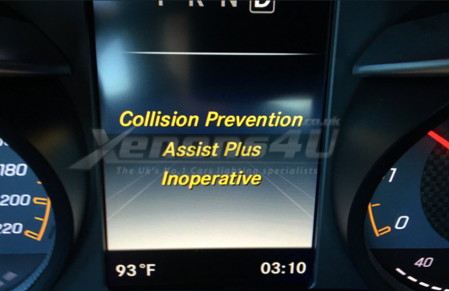
When the Collision Prevention Assist Plus system shuts down, the most commonly stored fault code is U105CFC. This is a Mercedes-specific UDS network fault code — the “U” prefix indicates a communication fault rather than a component failure.
Fault: U105CFC — Lost communication with CAN Bus participants
Status: Active and Stored
Related faults commonly stored simultaneously:
B2B4E14 — Relay coil Reserve: short circuit to ground or open circuit
B1E2113 — Buffer battery malfunction: open circuit
B1E211B — Buffer battery: current limit not attained
B219400 — Power supply circuit 30: < 7.5V ← auxiliary battery critical indicator
B219600 — Power supply circuit 30g: < 7.5V ← confirms voltage fault

What U105CFC tells you: The radar module (A90) lost communication with the CAN Bus. This is almost never a failed radar unit — it is almost always a power or communication issue. The fault codes B219400 and B219600 (circuit 30 voltage below 7.5V) appearing alongside U105CFC confirm the auxiliary battery is the root cause in a large proportion of cases.
How Collision Prevention Assist Plus Works
The system uses a forward-facing radar sensor (IC Radar, component designation A90) mounted in the front of the vehicle to continuously measure the distance and closing speed to vehicles ahead. It operates above 7 km/h (≈4 mph) and works in three stages:
- Warning stage: Visual and audible alert to the driver of an impending collision.
- Brake preparation: The system pre-charges the brake system for maximum deceleration response when the driver brakes.
- Autonomous braking: If the driver does not react, the system applies partial or full brake pressure automatically.
The A90 radar module communicates with the ESP control unit, Front SAM, and DISTRONIC control units via CAN Bus and FlexRay. It requires accurate wheel speed data from the ESP module to calculate closing rates and braking intervention timing. This is why faulty wheel speed sensors — even those that seem to “work” — can disable the entire collision prevention system.
All Common Causes — Ranked by Workshop Frequency
| Rank | Cause | Key Indicator | Fix |
|---|---|---|---|
| 1 | Dirty or obstructed radar sensor | Fault appears after rain, snow, or car wash. Clears after cleaning. | Clean radar emblem/bumper area. Recalibrate if moved. |
| 2 | Weak or dead auxiliary battery | U105CFC + B219400/B219600 stored. Multiple ADAS faults simultaneously. | Replace auxiliary battery with OEM unit. Clear all codes. |
| 3 | Radar sensor misalignment | Fault after bumper repair, accident, or bodywork. | Realign to OEM specification. ADAS calibration with targets. |
| 4 | Aftermarket wheel speed sensors | Live data shows 65535 km/h when stationary (should be 0). | Replace with genuine OEM sensors. Verify live data after. |
| 5 | Wiring harness connector corrosion | Intermittent fault — worse in wet weather. | Inspect and clean radar harness connector. Check Front SAM connectors. |
| 6 | Software mismatch / coding error | Fault after module replacement without proper coding. | Recode replacement module via XENTRY. Apply available software update. |
| 7 | Faulty IC Radar (A90) module | All other causes eliminated. Fault persists after calibration. | Replace A90 radar module. Code and calibrate with XENTRY. |
Radar Sensor Location — Model by Model
“Mercedes collision prevention assist plus sensor location” is one of the most searched queries related to this fault — and the answer varies by model. Here is a clear breakdown:

| Model | Radar Location | Access Method |
|---|---|---|
| C-Class W205, W204 late | Behind Mercedes star emblem — centre grille | Carefully remove star emblem (clips) — radar sensor behind |
| E-Class W212, W213 | Behind Mercedes star emblem — centre grille | Remove emblem — sensor directly accessible |
| GLC X253 | Behind Mercedes star emblem — centre grille | Remove emblem — sensor directly accessible |
| A-Class W176, W177 | Lower front bumper — behind grille mesh | Remove lower grille insert or bumper section for access |
| GLA X156, X247 | Lower front bumper — behind grille mesh | Remove lower grille for sensor access |
| CLS W218, W257 | Behind front bumper — lower fascia | Partial bumper removal required for sensor access |
| S-Class W222 | Behind front bumper — integrated into lower fascia | Workshop access — bumper removal required |

Case Study 1: Mercedes C300 — Collision Prevention Assist Plus Inoperative After Bumper Repair

Diagnostic Findings
XENTRY quick test revealed stored fault codes in the IC Radar (A90) control unit: radar alignment out of range, and CAN signal loss between IC Radar and ESP. Visual inspection confirmed the radar sensor bracket had been slightly bent during bumper installation — even a small angular deviation from OEM specification is enough to disqualify the radar beam pattern and disable the system.
Repair & Outcome
The radar sensor bracket was carefully straightened to OEM angle specification. The sensor connector was inspected and confirmed clean. The system was recalibrated using ADAS calibration targets — this step is mandatory after any physical radar movement, even if the sensor appears to be in the original position.
After calibration, the fault cleared automatically. Road test confirmed full operation of Collision Prevention Assist Plus and Active Brake Assist.
Case Study 2: Mercedes CLS W218 — Aftermarket Sensors & Dead Auxiliary Battery

This is our most instructive case — a Mercedes-Benz CLS 550 W218 that had already had the ESP control unit, engine ECU, and wheel speed sensors replaced by a previous technician — yet the “Collision Prevention Assist Plus Inoperative” warning persisted. This is a textbook example of parts-replacement diagnosis going wrong.
Step 1 — Wheel Speed Sensor Live Data
Rather than replacing more parts, the diagnostic approach started from the beginning — live data first. Checking all four wheel speed sensors with the Autel MaxiSys immediately revealed the problem:

The value 65535 km/h is the maximum possible value in a 16-bit data field — it means the sensor is sending a fault/overflow signal, not a real speed reading. The ESP module relies on accurate wheel speed to calculate deceleration and braking intervention. With two front sensors reporting maximum speed when stationary, the ESP correctly identified a sensor fault and disabled collision prevention.

The root cause: the previously installed “replacement” wheel speed sensors were aftermarket units that did not meet Mercedes CAN Bus signal specifications. They generated the correct voltage but incorrect signal encoding.

Step 2 — ADAS Fault Persists After Sensor Fix
Despite resolving the wheel speed sensor issue, the Collision Prevention Assist Plus warning remained. A full system scan showed no remaining CAN communication faults between radar and ESP — pointing to a power supply issue rather than a signal problem.
Step 3 — Auxiliary Battery: 0.47 Volts

The auxiliary battery at 0.47V was causing intermittent CAN Bus dropouts — the fault codes B219400 and B219600 (circuit 30 voltage below 7.5V) confirmed this. The Front SAM unit was experiencing short-circuit-to-ground conditions due to the critically low battery voltage, which disrupted the entire ADAS power distribution network.

Step 4 — Repair & System Restoration
- 1Both front wheel speed sensors replaced with genuine OEM Mercedes-Benz units. Live data confirmed all four sensors reading 0 km/h stationary.
- 2Auxiliary battery replaced with new OEM-certified unit. Battery terminals and Front SAM connectors cleaned and inspected.
- 3Electrical system reset via XENTRY Diagnostics. All fault codes cleared in ESP, IC Radar, Front SAM, and related modules.
- 4ADAS calibration performed — radar beam alignment verified with calibration targets.
- 5Road test: Collision Prevention Assist Plus reactivated automatically. Radar, ESP, and emergency braking confirmed fully operational.
Step-by-Step Diagnostic Guide
| Step | Check | Tool | Pass | Fail → Action |
|---|---|---|---|---|
| 1 | Radar sensor visual inspection | Visual | Clean, no obstructions, no physical damage | Clean gently. If after bodywork — check alignment. |
| 2 | Auxiliary battery voltage | Multimeter | >12.4V at rest, >9V under load | Replace auxiliary battery first. Clear codes and retest. |
| 3 | Main battery load test | Battery load tester | >12.4V under EPS and ignition load | Replace main battery if weak. |
| 4 | Wheel speed sensor live data | XENTRY / Autel | All four sensors: 0 km/h stationary, smooth rise when moving | 65535 reading = aftermarket/faulty sensor. Replace with OEM. |
| 5 | Full system fault scan | XENTRY / Autel MaxiSys | No U105CFC, no B219xxx codes | Address faults in order: power → sensors → communication → radar. |
| 6 | Radar connector inspection | Visual + multimeter | Clean pins, secure seating, no corrosion | Clean connector, apply dielectric grease, reseat. |
| 7 | Radar alignment check | ADAS calibration equipment | Within OEM angle specification | Realign and recalibrate. Mandatory after any front-end work. |
| 8 | Software / coding check | XENTRY | All modules on current software, correctly coded | Apply update. Recode if module was replaced. |
How to Clean the Radar Sensor
A dirty radar sensor is the quickest and cheapest fix — and it resolves a significant proportion of temporary Collision Prevention Assist Plus faults. Here is the correct method:
- 1Switch off the vehicle completely before touching the radar area.
- 2Locate the sensor — behind the star emblem on most C-Class, E-Class, GLC models; lower bumper area on A-Class and GLA. See the location table above.
- 3Inspect for obstructions — mud, snow, ice, insect debris, or aftermarket bumper film/wrap over the radar zone.
- 4Clean gently with a damp microfibre cloth and mild automotive cleaner. Never use harsh chemicals, solvents, or high-pressure water directed at the sensor.
- 5Remove any film or wrap covering the radar zone — even transparent film blocks radar signals significantly.
- 6Dry thoroughly with a clean microfibre cloth. Restart the vehicle and check if the warning clears.
- 7If the warning does not clear after cleaning — the cause is not dirt. Proceed to the full diagnostic sequence above.
Frequently Asked Questions
— Salim, Mercedes Expert
Independent specialist in Mercedes-Benz diagnostics, CAN Bus analysis, troubleshooting case studies, and EV systems.